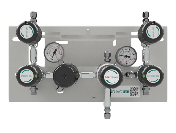
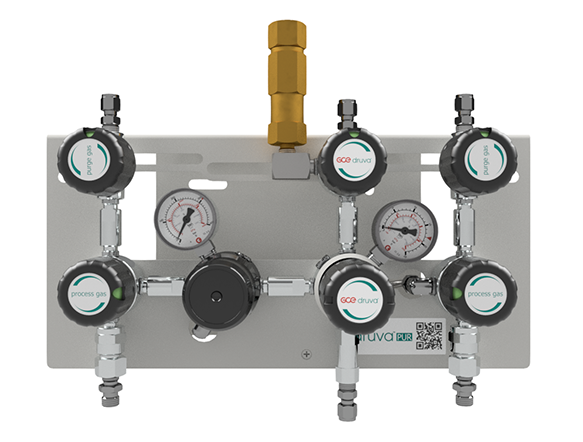
LOW FLOW RANGE - DUAL STAGE - PROCESS GAS PURGING SYSTEM
MANIFOLD FOR PURE GAS SUPPLY SYSTEMS, Two sources, Manual change over system, Process gas purging system
The manifold used in gas supply systems for pure, inert, flammable, oxidizing gases and gas mixtures. Not usable for corrosive and/or toxic gases and gas mixtures. Maximum gas purity is 6.0.
TECHNICAL SPECIFICATION
- Switching between two sources by the manual valve actuation
- Regulator and Valves - Hastelloy/Elgiloy diaphragm tighting system to atmosphere
- Compact design
- Excellent pressure adjustment
- Valves - designed and approved in accordance with relevant sections of EN ISO 10297:2015 (including O2 - ignition test for the main valve)
- Regulator - designed and approved regarding ISO 7291 (including O2 - ignition test)
- A relief valve in the delivery pressure side
- Manifold with purge valve for process gas purging
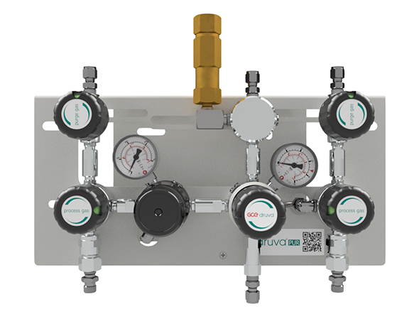
- Available with a shut-off valve at outlet, safety valve at outlet, check valve at the inlet
- Electrostatic chargeabitlity test
- Fulfils requirements according to DIN EN ISO 80079-36, IEC TS 60079-32-1 and German TRGS 727
- Usable in Ex-areas zones 1 and 2 for gases with explosion risk group I, IIA, IIB, IIC
SPECIAL FEATURES OF MANIFOLD
- Splitted plates of the manifold
- Separated mounting of the ground plate
- Easy mounting of the manifold to ground plate and fix with one screw only
- Front plate cutout for in-field gauge replacement
TECHNICAL DATA
| Working temperature: | -20°C to +60°C |
| Material: | Brass chrome plated or Stainless steel |
| Material bracklet: | Stainless steel |
| Flow nominal: | 20m3/h (N2) according to ISO 7291 at 20 bar outlet pressure and 41 bar inlet pressure |
| Pressure rates manifold: | |
| Max. inlet pressure: | 300 bar |
| Delivery pressure: | 2/3/6/10/14 bar |
Technical datasheets
Direct link to druva product configurator
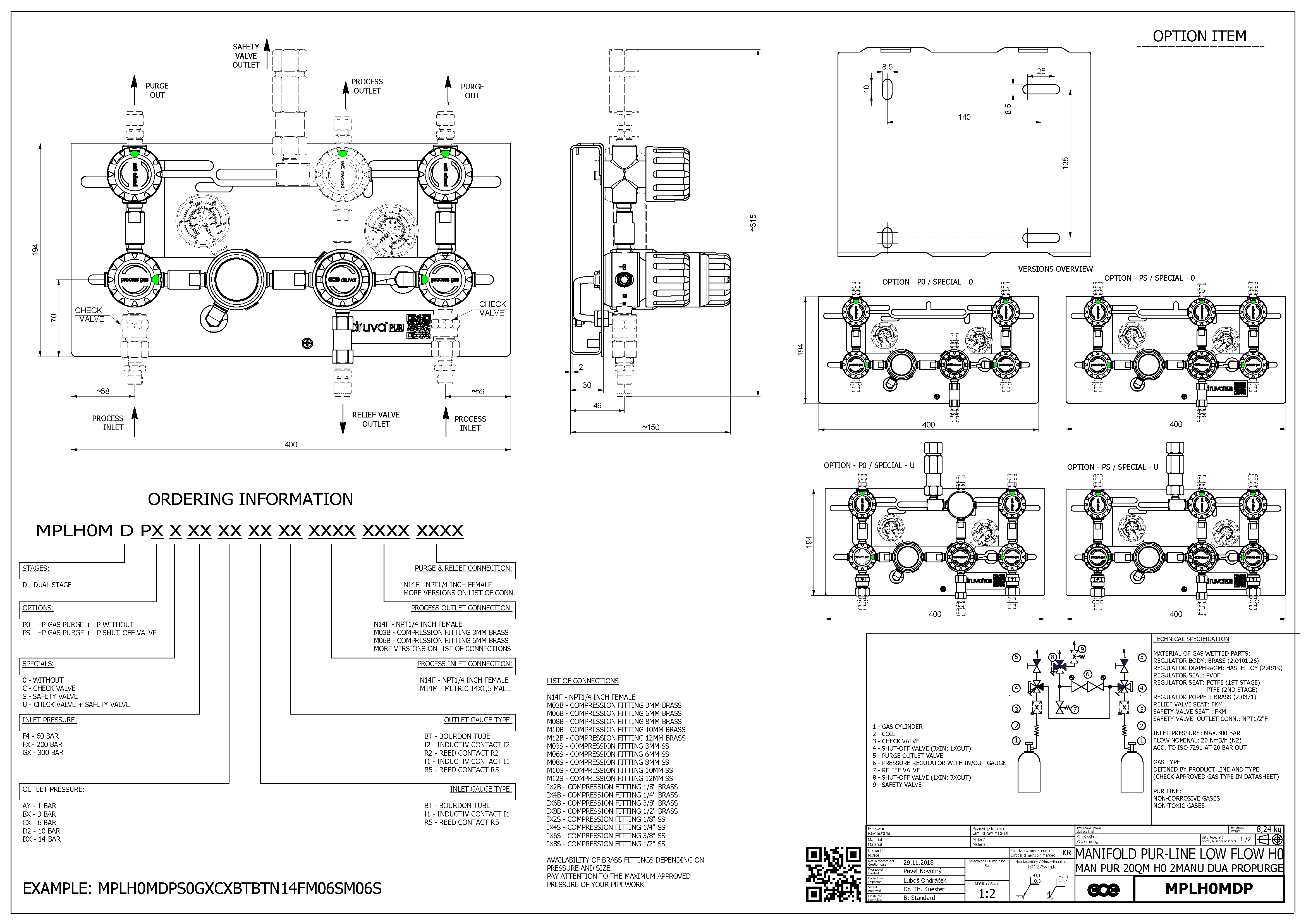
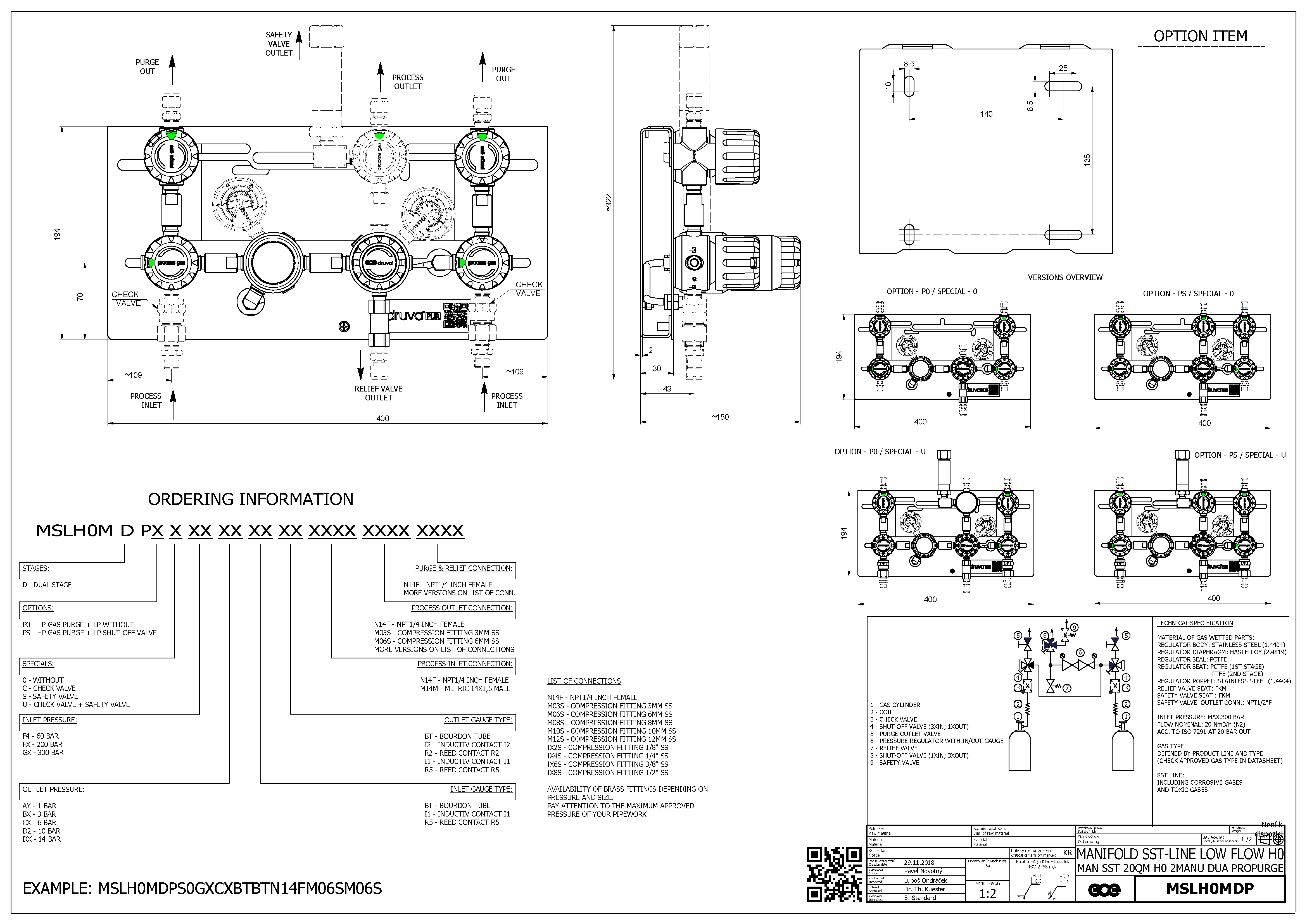
Technical Drawings
Top
Download Technical Drawings

