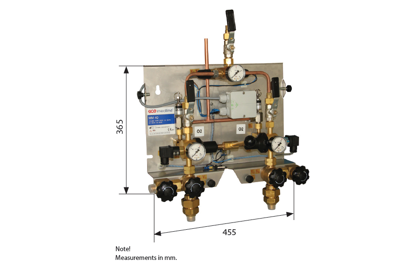
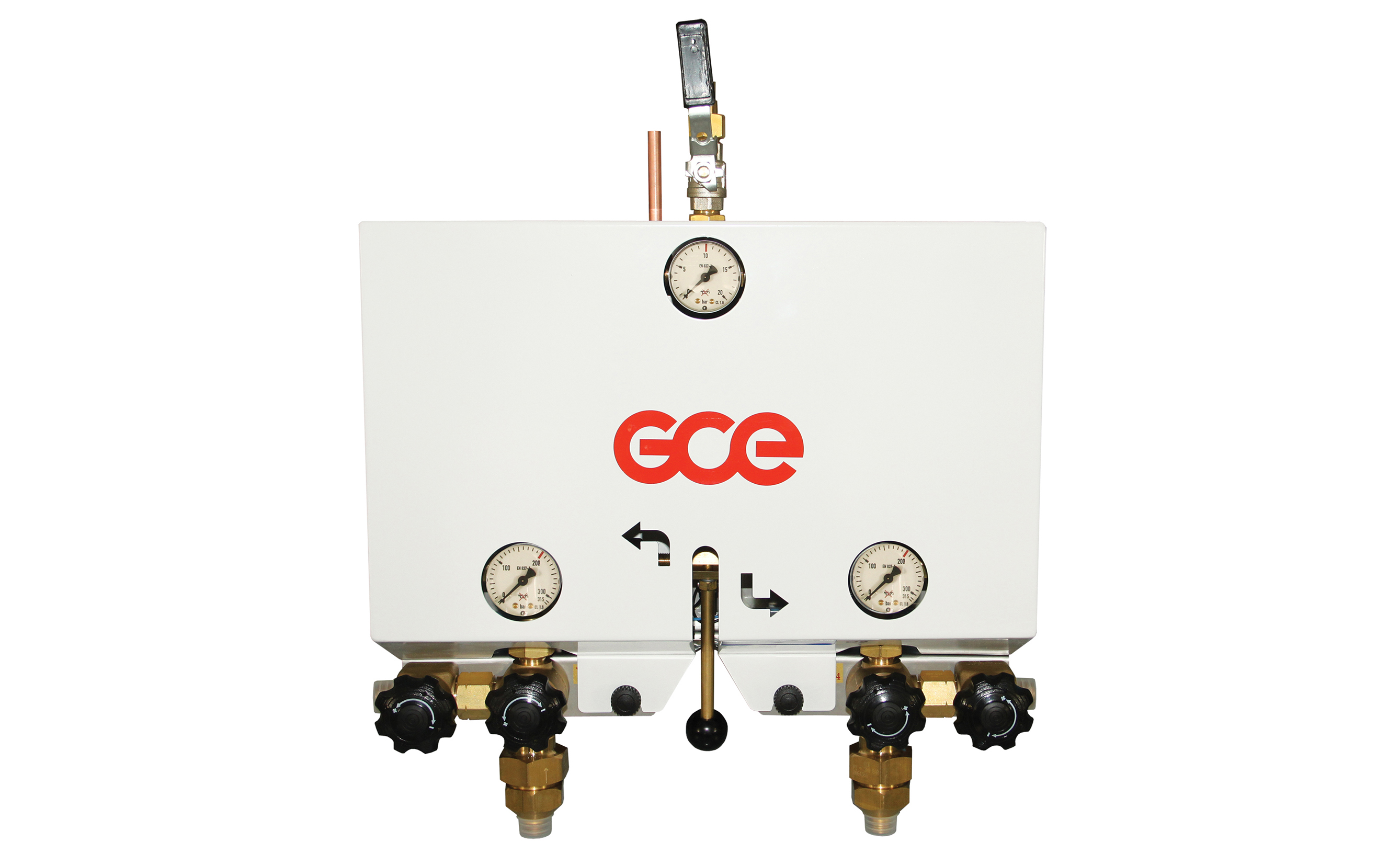
GAS MANIFOLD MM40 - HP UNIT
Group Number: 3611Whole medical range is available on
Manifold MM40 HP unit is an automatic manifold. It is working on the principal of different pressures between the operation and reserve regulator. By the manual lever, the operator can decide which side will be the operational side and which will be the reserve side. When the operating side is empty, the manifold will without any action start to supply gas from the reserve side with the lower regulator pressure and fulfilll the requests to supply without interrupting the flow.
MM40 HP unit manifolds together with a stabilizer should be used as second and third source of gas in systems with liquid gas tank. For hospitals without liquid gas tanks it is possible to use manifold MM40 HP unit together with a stabilizer as first and second source, and in connection with a third source (MM90 Standby) it will provide a final solution to fulfill ISO 7396-1 and national installation standards.
Manifolds are supplied with an Alarm system which increases safety to maximal level and informs the hospital personal about each non standard situation.
Gas Alarm is a standard accessory. The gas alarm gives visual and audible indications.
It surveillance and sounds the alarm when the following happens:
1. Leaking reserve side
2. Empty possition (High/Low distribution pressure when connected to a Stabilizer)
3. Change operation side
4. High intermediate pressure
-
The gas alarm is able to communicate with other equipment through relays.
-
Manifold MM40 is only first stage of regulation and must be installed together with a Stabilizer which will stabilize the final pressure used in the hospital gas outlets.
-
GCE medical manifolds are CE-marked and fulfill the ISO 7396-1 standard.
 735100000691 MM40 HP unit leaflet EN
TECHNICAL DATA
| Gases: | O2, Air, N2, N2O, CO2 (all medical gases) |
| Nominal flow: | 40 m3/h |
| Inlet nominal pressure: | 200 bar |
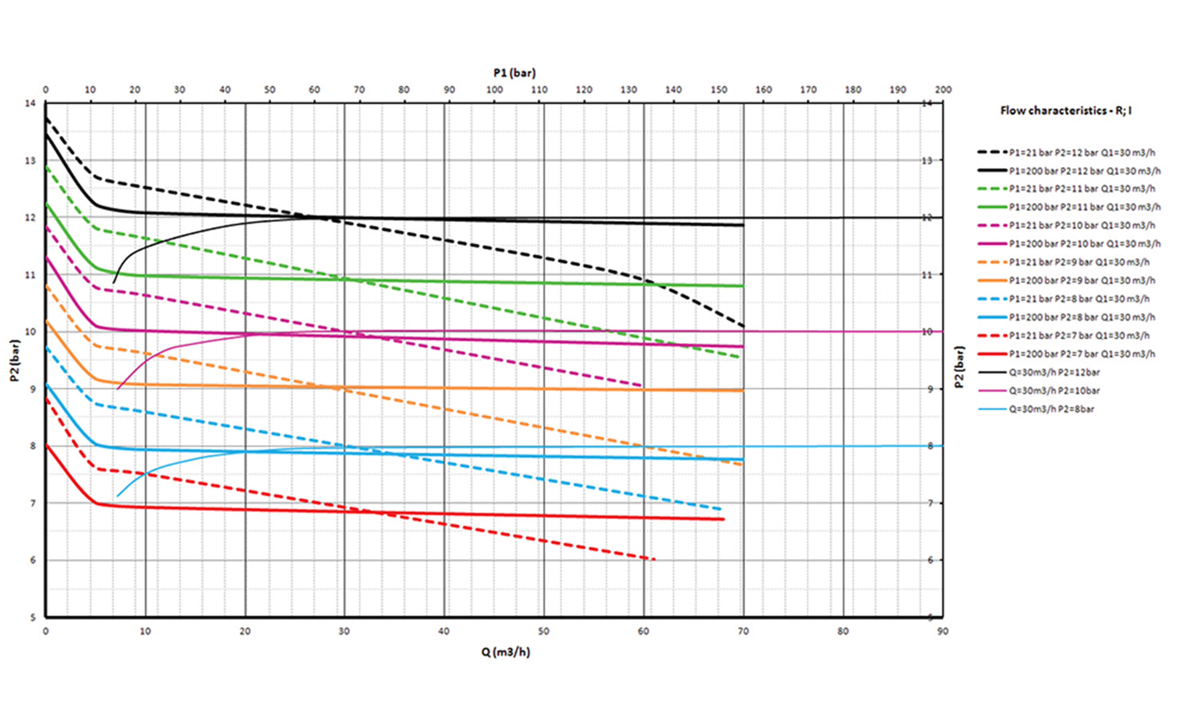
| Outlet nominal pressure: | 12 bar (setting range 9–16 bar) |
| Inlet connection: | W21,8×1/14"M |
| Outlet connection: | G1/2"M + Soldering piece pipe Ø 10, Ø 15 mm |
| Pressure relieve valve: | 17 bar |
| Pressure relieve valve pipe dimension: | Ø 10 mm |
| Purge valves connection: | W21,8×team1/14"M |
| Regulatory status: |
Complies with Medical Devices Directive 93/42/EEC |
SPECIFICATION
MM40 INCLUDES THE FOLLOWING COMPONENTS:
- MM40 HP unit Manifold
- Gas alarm
- Purge valves
- HP filters
- Shut-off valve for distribution line to stabilizer
FOR A COMPLETE MM40 HP UNIT MANIFOLD ADD:
- Collecting pipe set (high pressure valves, non-return valves/high pressure components)
- Cylinder retaining brackets (included in gas cylinder collecting pipe set)
- High pressure hoses with safety wire
- Plug for close collecting pipeline
- Gas name sign
- Stabilizer
| Item No. | Denomination | Gas | PRV | Alarm |
| 0732307 | MM40 – HP unit 2×1 | O2, Air, N2 | Standard | Alarm TMA6703 |
| 0732308 | MM40 – HP unit 2×1 | O2, Air, N2 | With pull-ring | Alarm TMA6703 |
| 0727334* | MM40 – HP unit 2×1 | O2, Air, N2, N2O, CO2 | Standard | — |
| 0732310 | MM40 – HP unit 2×1 | N2O, CO2 | Standard | Alarm TMA6703 |
| 0732311 | MM40 – HP unit 2×1 | N2O, CO2 | With pull-ring | Alarm TMA6703 |
| 0727371** | MM40 – HP Unit 2x1 | O2, Air, N2 | Standard | 4-20mA |
* basic version without electronic sensors
**ISO standard version without Leaking reserve as requested for HB370


